
MS Formwork: Separate the Shuttering, Centering, and Support Requirements
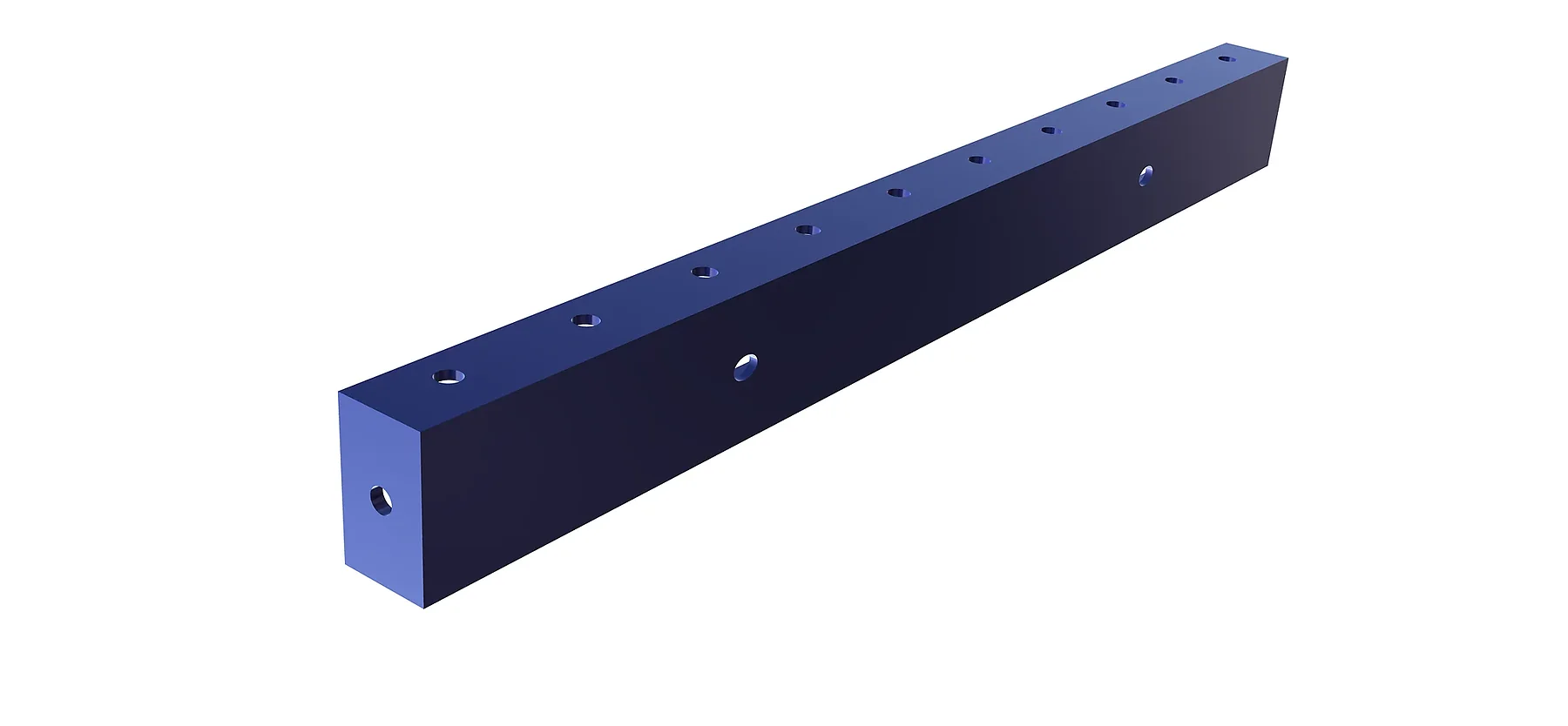
MS formwork is easier to specify when the work is divided by the concrete surface being formed and the load path being supported. The Schach brief catalogue distinguishes shuttering for vertical concrete surfaces from centering for horizontal surfaces, then presents the component families used to connect and support them.
Shuttering forms vertical surfaces
Wall sides, column sides, retaining walls, cores, and similar vertical elements require panels that resist fresh-concrete pressure and transfer that action through ties, wallers, soldiers, braces, and supports. Straight panels address regular geometry, while internal corners, external angles, kicker corners, and special panels close the junctions.
Centering supports horizontal surfaces
Slab bottoms and beam bottoms require a support arrangement beneath the concrete. Props, drop heads, beams, ledgers, and connecting components must be selected as one load path. The spacing and permitted loading cannot be inferred from a component photograph; they belong in the engineered layout for the actual slab, beam, height, and pour sequence.
Reinforcement components are not interchangeable labels
Soldier panels and wallers stiffen and align panel arrangements. Tie rods, disc nuts, clamps, pins, wedges, and connectors transfer or close forces at defined locations. Foot and top adapters connect support members to the assembly. Each item needs the correct size, spacing, finish, and compatibility with the selected panel system.
Curved and heavy geometry needs an early review
Round columns, curvature panels, heavy square or rectangular columns, lift walls, and one-sided retaining walls should be identified before a standard panel schedule is prepared. Radius, concrete pressure, access to connections, lifting method, pour height, and available reaction points can change the arrangement substantially.
Send information by work package
For walls and columns, share plans, sections, heights, thicknesses, pour rate, concrete pressure basis, corners, openings, and access constraints. For slabs and beams, add slab thickness, beam sizes, soffit levels, support height, loading basis, striking and reshoring requirements, and the proposed pour sequence.
Ask for the complete configuration
A useful proposal should identify the panel arrangement, strengthening members, ties and connectors, support system, access provisions, planned reuse, finish, and any project-specific fabrication. Final quantities and allowable loads should follow approved drawings and calculations.
Treating MS formwork as a connected system prevents the common mistake of selecting visible panels while leaving the supporting and connecting components to be resolved later on site.