
When a Standard Tower Is Not Enough: Planning Customized Scaffolding
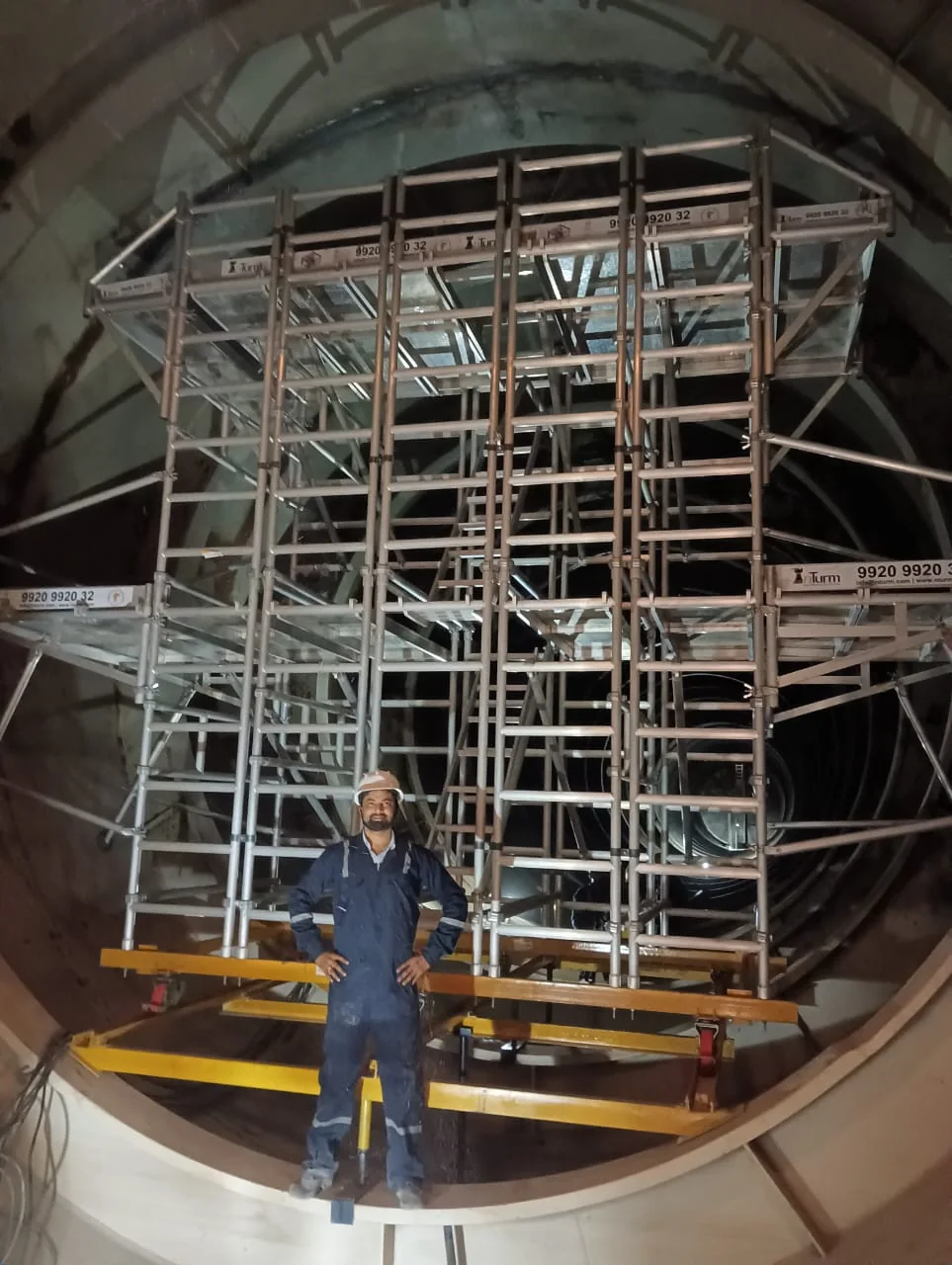
Standard modular towers work well when the access zone is regular and the required platform fits the available footprint. Customized scaffolding begins when the work face, structure, or operating environment prevents that regular arrangement. Schach catalogue examples include bridge arrangements, tunnel access, connected aluminium towers, cantilevers, industrial access, and multi-directional modular systems.
Survey the actual work face
Record plan dimensions, height, platform levels, access points, openings, slopes, and the surface supporting the scaffold. Photographs should show the entire work zone as well as close views of obstructions and possible tie or stabilizer locations. A circular tunnel, for example, changes the available width at every level.
Define what the platform must support
State the number of users, tools, material, and any concentrated equipment loads. Identify whether one level or several levels will be loaded at the same time. The platform duty and support arrangement must be confirmed for the actual configuration; a catalogue tower rating should not be transferred to a custom assembly without review.
Map obstructions and interfaces
Pipes, process equipment, beams, facade projections, live traffic, finished interiors, tracks, and temporary services can interrupt the scaffold grid. Mark required clear zones and the points where the arrangement may or may not connect to the permanent structure.
Choose the system after the geometry is understood
Aluminium towers suit lightweight, mobile, and corrosion-resistant access where their dimensions and loading are appropriate. Cuplock supports repetitive modular grids. Ringlock offers multi-directional connection points for changing geometry. H-Frame provides a straightforward repeated frame arrangement. Pipe & Coupler can adapt around irregular interfaces. A custom solution may combine standard components with project-specific platforms, brackets, or bridging elements.
Plan access as part of the scaffold
Stair units, internal access, trapdoor platforms, rest levels, gates, toe boards, guardrails, and material-loading points should be included in the initial configuration. Adding them later can change bay dimensions, loading, or bracing.
Review erection and movement
Document the erection sequence, exclusion zone, inspection stages, tie installation, relocation method, and dismantling route. For mobile aluminium systems, floor condition, castors, stabilizers, movement restrictions, and overhead clearance are essential.
Information for a useful first proposal
Send drawings or measured sketches, working height and length, platform levels, intended duty, site photographs, ground or floor conditions, obstructions, tie restrictions, project location, programme, and any client standards.
Customization should mean an engineered response to site geometry, not an improvised collection of components.